
Help with Bearing Calculator - User Bearing Arrow Input
The bearing prediction calculator can be used to generate a triangulation back towards a causal impact site.
You can create your own triangulation kml for a favorite Carolina bay, to visualize a triangulation attempt in Google Earth. The user places an alignment overlay in Google Earth, and the calculator uses that as input. The generated output is a kml containing data elements. The process is relatively simple:
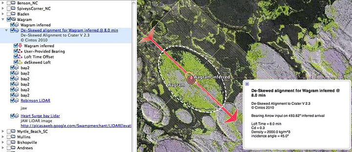
Locate an area of interest within a bay or field of bays. We suggest you begin by referencing one of the entries in the Distal Ejecta Fields kml file. In this example, we used the Wagram field location. The kml includes a color-ramp elevation overlay of the area, which may help you in identifying an appropriate inferred arrival bearing. We use a set of overlays to highlight the bay outline, as seen below with a dashed white oval. If you open the suggested kml file, this overlay will be in place.
If you previously used the calculator to create a set of Predicted Bearings, the Bearing Arrow Overlay would already be in position at the bay.
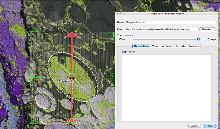
Beginning at a candidate bay, add the Bearing Arrow overlay { Add Overlay }
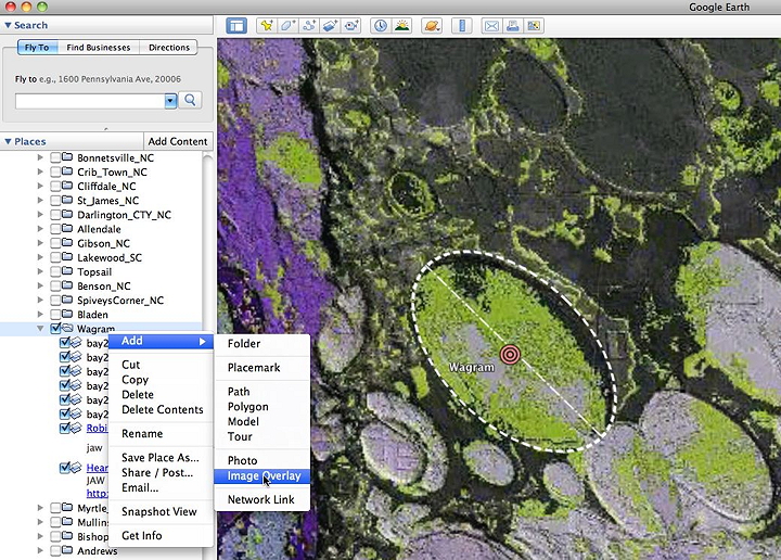
Add a helpful name to the overlay, and Link to the Bearing Arrow overlay [ http://cintos.org/ge/overlays/Bearing_Arrow.png ]
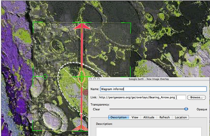
The arrow will initially place facing towards an arrival bearing of zero.
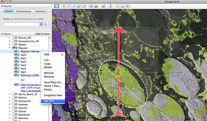
With the overlay selected [ Get Info }, move the center of the verlay so that it is centered in the bay in question.
Then use the small handle box to rotate the arrow into alignment with the bay or field of bays.
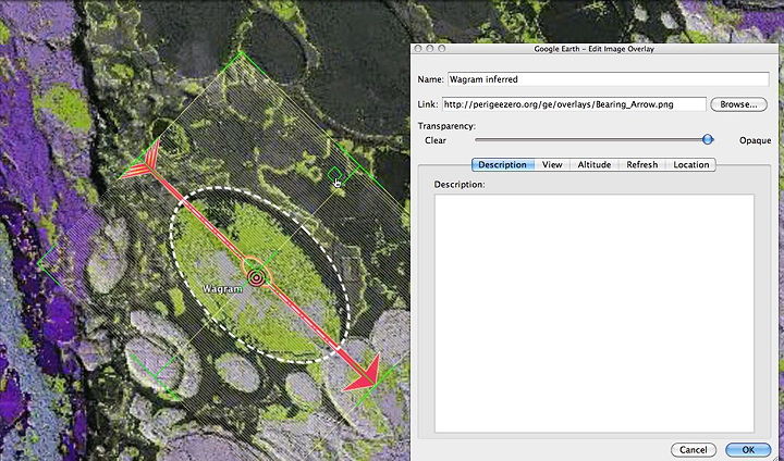
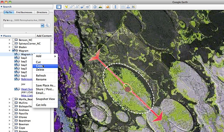
When you are satisfied with the alignment, use the copy function to place the overlay's kml on the clipboard.
Next, access the calculator at http://cintos.org/java/PredictBearings.html
Proceed to the Bearing Calculator Web Applet page and paste the copied Bearing Arrow kml data into the input window. (clear out any prior entries: select-all & delete). Chose different input parameters, or leave them at the default. For a solution to be valid, all members of a set should use identical parameters. Click the "generate" button.
Click into the result window at the bottom, and { select all } & { copy } to place the generated kml on the clipboard.
Finally, go back to Google Earth and paste in the kml.
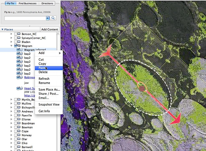
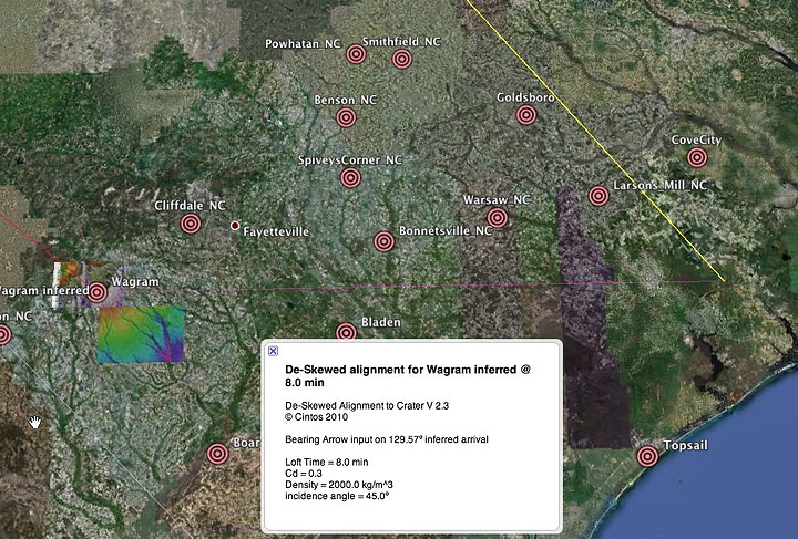
The new kml is titled with the loft time and your chosen name. Expand the item to see the elements. Clicking on the title will yield a pop-up box with more details fo the solution set.
The defaults for a solution set are pre-set in the calculator window; they should generate a bearing line (yellow) which points back towards the implied impact site. In addition, the user input line is re-created (red) , along with the eastward offset controlled by the loft time (purple).
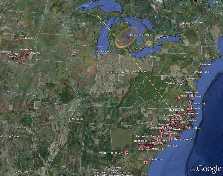
Note! For a solution set to be valid, we are assuming that all variables need to remain constant across an entire collection of bays. While these variables may be different at different locations and ejection points along the crater ramparts, tuning individual bays for correct alignment would compromise the validity of the model. If you wish, re-run your bearing path with different input variables. There exists a wide range of loft time vs terminal velocity that will result in a Saginaw bay focus. The parameters used in any simulation are embedded in the calculator's output kml.

Geological Research by Cintos is licensed under a Creative Commons Attribution-NonCommercial-ShareAlike 3.0 Unported License.
Based on a work at Cintos.org.
Permissions beyond the scope of this license may be available at http://cintos.org/about.html.