
Help with Bearing Calculator
The bearing prediction calculator can be used to generate arrival bearing lines to compare with actual bay landforms at any given location. Used in conjunction with Google Earth, the generated lines are kml data packets. At this time (12/2016), the on-line version is not functioning due to security updates to the JAVA tools. I hope to correct the code indiscretions soon.
You can create your own kml for a favorite Carolina bay, to visualize our prediction of orientation in Google Earth. The process is relatively simple:
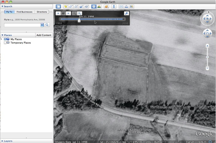
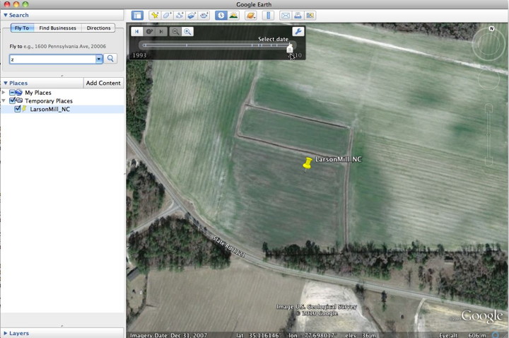
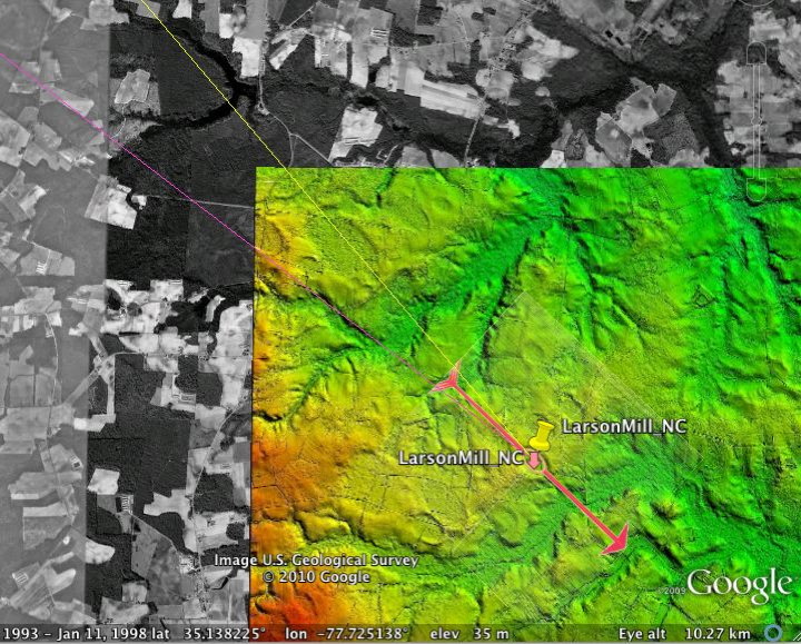
Locate a likely bay candidate in Google Earth. Here, we are using older b&w image data, which often brings out bays from the background imagery. One good place to start is with the GE forum post "Comprehensive SouthEastern US Crater catalog" by Thomas Flores, which contains kml placemarks for over a thousand likely Carolina bay locations (along with a few crop circles :)
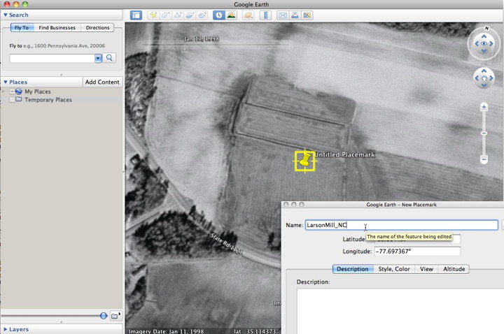
Create a placemark { Add Placemark } near center of bay, as you percieve it to be.

Add a useful name to the placemark for reference. The Description field can be used for additional info.
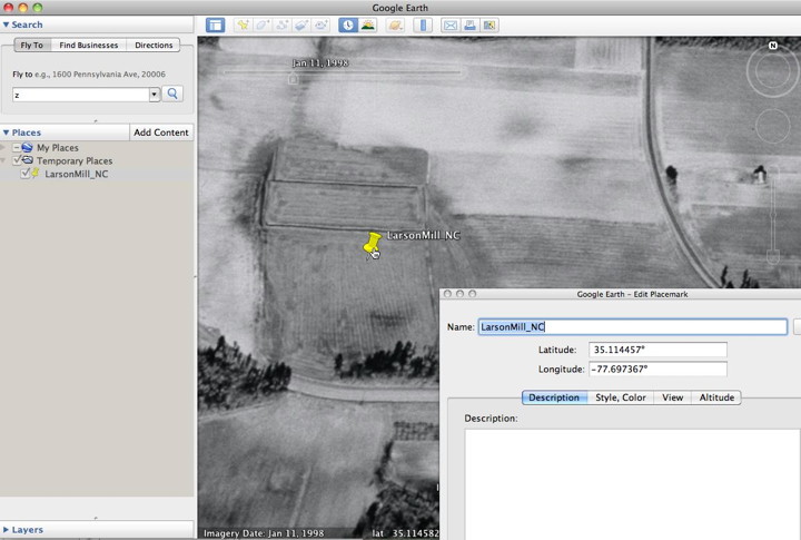
Use "Get Info" to edit the placemark, dragging it to reposition if necessary
Here, we change to most recent imagery to verify the selection and positioning.
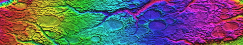
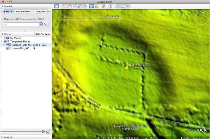
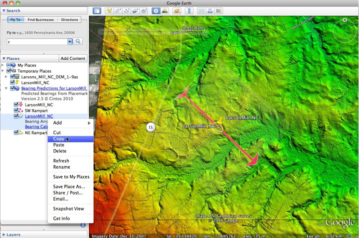
Color ramp digital elevation mapping (DEM) imagry is often used by us to get an even more solid verification of the bay's geometry.
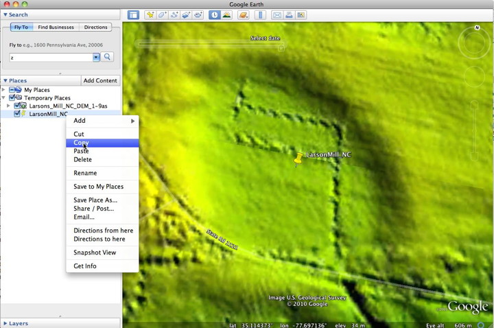
Use the copy function to place the placemark's kml on the clipboard.
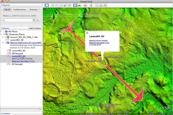
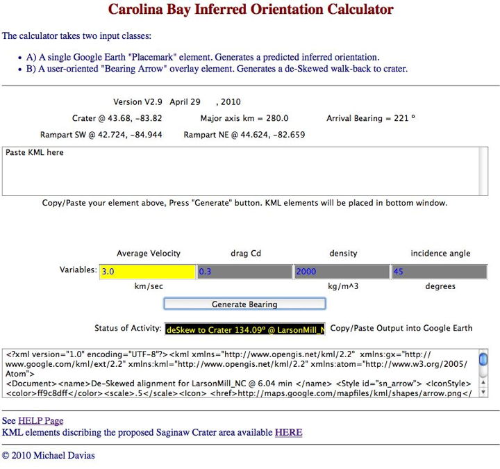
Next, access the calculator and paste the copied kml data into the input window. Click the "generate" button. The Status window should show "Predicted Bearings for ..." Click into the result window at the bottom, and { select all } & { copy } to place the generated kml on the clipboard.
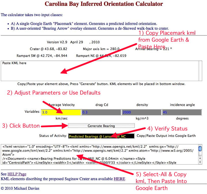
Finally, go back to Google Earth and paste in the kml.
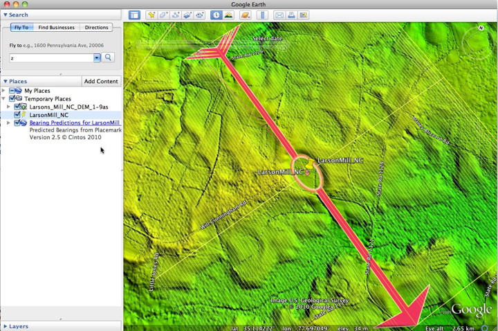
Expand the Bearings Predictions folder to see detail. The "Bearing Arrow" overlay should be aligned closely with the bay. It is delivered as a fixed size (box ~ 4km diagonal), and would likey need to be edited (Get Info) to adjust it to the size of the bay/bays in question.
The defaults for a solution set are pre-set in the calculator window; they should generate a set of accurate bearings. We expect to see orientations bound by the yellow (NE) and purple (SW) bearing lines, representing the crater rampart extremes. While individual bays may be erratic, a field of many bays should correlate to our predicted bearing range.
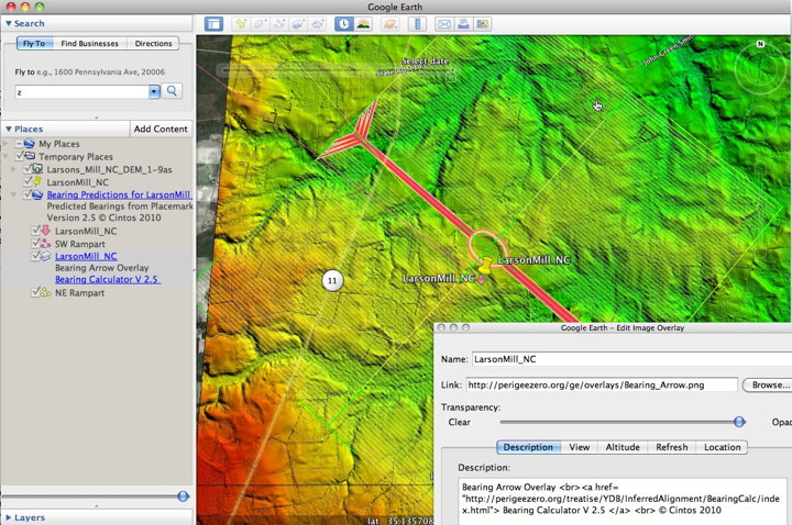
With a set of bearing lines and the Bearing Arrow in place, the user can continue the exploration by adjusting the BearingArrow so that it represents the user's interpretation of the bay's or bay field's inferred orientation. The Arrow can then be input back into the calculator to generate the numerical model's actual de-skewed trajectory. Below, we edit the Arrow overlay, rotating it as required with the small handle, and dragging the grid around to match up best fit to all available bays.
When you are satisfied that the Bearing Arrow represents your inferred alignment, copy the overlay object to the clipboard.
Access the calculator again, this time pasting the overlay kml into the input window. Be sure to clear out any previous entires. Click the "Generate" button, and then select-all and copy out the output kml text from the bottom window. The status window should verify that a deSkew to Crater kml set was generated.
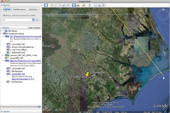
Paste the kml into Google Earth to view the de-skew walk back. A red path will re-trace the inferred bearing line for verification. A purple path will run east to the non-rotating earth target position, and a yellow path will run from there back towards the causal impact site.
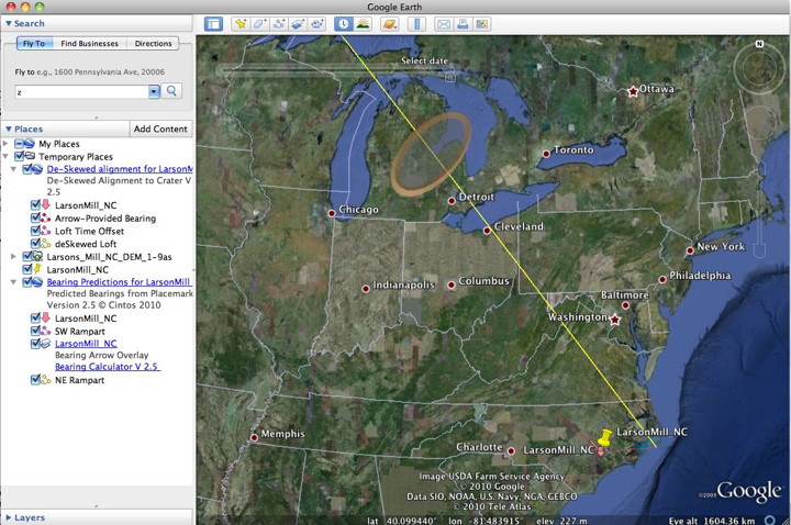
The last graphic here shows the trajectory path intersecting the proposed Saginaw Impact crater outline. By generating many such trjaectories, both in the east and in the west, a triangulated solution should appear. The Saginaw crater kml is available HERE.
Note! For a solution set to be valid, we are assuming that all variables need to remain constant across an entire collection of bays. While these variables may be different at different locations and ejection points along the crater ramparts, tuning individual bays for correct alignment would compromise the validity of the model. If a parameter change is desired, then run all test bays again with those settings.

Geological Research by Cintos is licensed under a Creative Commons Attribution-NonCommercial-ShareAlike 3.0 Unported License.
Based on a work at Cintos.org.
Permissions beyond the scope of this license may be available at http://cintos.org/about.html.