
Systematic by Latitude
Resolves On ContactWhile the Coriolis Force component is systematic by loft time, there is another factor superimposed on alignment that is systematic by latitude. In the first case, the earth rotates at 0.25 degrees of longitude per minute, regardless of where on the earth the consideration is applied. In our second case, we rationalize that the ground speed of any particular spot on the earth is a function of the cosine of its latitude. The end cases are the poles - where the ground velocity w>e due to rotation is negligible - and the equator - where the ground speed w>e is ~1,670 km per hour.
In our specific Saginaw Manifold, a relevant set of w>e velocities would be our Saginaw Centroid point - rotating at 1,270 km/hr - and a generic ejecta field such as Bishopville - rotating at 1382 km/hr. At time of contact the 165 km/hr w>e velocity difference will resolved by a skewing of the "splat", effectively rotating the inferred bearing in the clockwise direction.
By way of explanation, a droplet of ejecta traveling from the North to the South in its great-circle frame of reference would not be affected by that ground speed difference until it approaches the surface of the earth, where the atmospheric breaking effect on terminal velocity would be applied. Across those last moment of the flight, the west-to-east ground velocities will be resolved. Given a point object such as a missile warhead, this resolution need not be considered. When an object as large as our posited ejecta droplets (say, 100m diameter) lands, this resolution will skew the inferred arrival bearing. In our cases the velocity difference needs to be subtracted from the inferred w>e velocity vector. Since the n>s velocity vector is constant, the effective alignment rotates clockwise slightly.
How relevant is this? It may be considered to be a minor factor in the more northerly fields, where there is less w>e velocity differential to detract form a relatively high w>e loft vector. In the more southern fields, the adjustment becomes a much higher factor both in magnitude, and in respect to the smaller w>e loft velocity vector. When superimposed on the counter-clockwise effect of the Coriolis (systematic by loft time), the latter may tend to overpower the former. We suggest that when moving north to south through the fields this general shift of the alignment vector clockwise is seen as "systematic by latitude". And the results of both the loft time and skew factors? Chaos within a bound set of results.
A relevant analogy would be the "Crab Angle" velocity vector required to compensate for cross-runway winds during an aircraft landing approach. Given high enough cross-winds, the visual effect can be stunning. Take a look at these four sequential photos of a 747 landing. Clicking the image will show the movie.
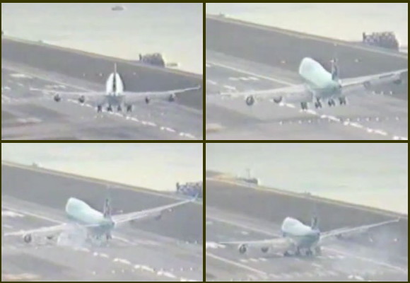
Click on image to see the movie
SEE Additional Movies HERE
In the case of distal ejecta, the land and atmosphere are moving rapidly west-to-east under the falling ejecta. During the terminal velocity atmospheric braking the latitude difference between the proposed crater's rim and the bay location create an W>E velocity delta because of the earth's spherical shape. That effect increases in magnitude as the landing sites move more southerly. At our most southerly field, Warner Robins, GA, the ground speed difference is 197 km/hr. Amplifying the latitude effect, the 197 km/hr delta is applied to a W>E loft velocity vector that is smaller relative the those of the more northerly fields, resulting in a higher percentage adjustment. The following graphic attempts to exhibit the numerical adjustments we make to the inferred alignment to arrive at a de-skewed bearing for each bay. The graphic uses the metrics of Wagram, NC's field.
As the heuristic solution continued, we have assumed that a compute model could be developed that would iteratively resolve for a set of ejecta loft parameters from the Saginaw Impact area (ejection site along butterfly, loft azimuth, loft angle, loft velocity) that would satisfactorily correlate each of the Carolina bay structures with the empirically measured results. To further that goal, we have created a numerical model to generate the great-circle lines necessary to plot the west-to east offset caused by the Coriolis force (systematic by loft time) and the earth-surface rotational speed differences (systematic by latitude). By using the model, we solved for a Saginaw area loci and generated the following visualization in Google Earth.
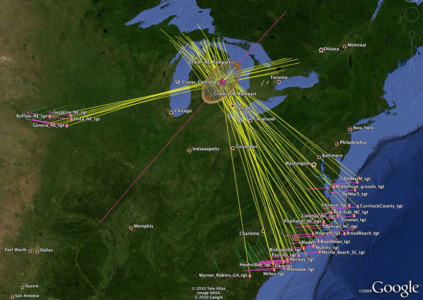
The elements generated include a short green line representing the measured inferred bearing at each field, a pink line to the east representing the loft time offset, a surrogate field placemark (tgt) representing the "stationary earth" trajectory target of the ejecta loft, and a yellow line representing a great circle line back from that target along the de-skewed arrival bearing.
A series of runs were made to bracket the correlated loft times and the expected terminal velocities. By adjusting for several variables, sets of those variables were identified which generate a satisfactory loci within the proposed Saginaw crater. Here is a graphic which attempts to represent the relationship between the atmospheric drag on the ejecta droplets (Cd) and the resulting terminal velocity and average trajectory ground-velocity for a series of Saginaw loft time solutions. This chart ws generated by varying the proposed loft time from 4 to 24 minutes, while varying the droplet Cd to reach a solution for all bays which align within the Saginaw crater ramparts.
The chart highlights the probable velocities and resulting loft times. Once the input variable for the average velocity exceeded ~2 km.sec, the terminal velocities required for a Saginaw loci solution approached a 200 m/sec asymptote. Empirically, this would suggest that the ground vector component of the terminal velocity of the ejecta was ~200 meters/sec. We believe that the 200-300 meters/sec range for terminal velocities that were identified are highly correlated to the ~360 meter/second value seen in a separate terminal-velocity calculation for a 100-meter diameter droplet of ejecta. Note that only the ground vector of the velocity is being considered in the de-skewing calculations, which would be lower than the total 3-d terminal velocity. The value of ground component would depend trigonometrically on the vertical angle of incidence that the ejecta approached at; these calculations assume a 45º angle.
Google Earth path sets for each of the plotted points in the chart above were generated to visualize the loci focus. The chart below is considered the most likely 'average" solution to the set. During the actual proposed impact, ejecta density and terminal velocities would likely vary by field.
The entire range of correlation charts for the solution sets are displayed in the Solution Charts sub section to this page.